Showing posts with label mod. Show all posts

Saturday, July 9, 2016

Hori Hayabusa and Hayabusa Silent Optical Joysticks

I was debating about even making a post about this because for some reason I felt like that this isn't entirely engineering related, but on the other hand it's also one of my hobbies. So let me lay out some of the details and we can see if this is useful to anyone else.

About four months ago(I think, I can't remember exactly) I purchased a Hori Hayabusa joystick and it works pretty well. It's somewhere inline with the JLF. This isn't really a review of the joystick. Anyways, a wonderful person known as Kowal through Shoryuken forums came up with a fantastic octagonal restrictor gate.

What a wonderful octopus
Hori Hayabusa Original w/ Kowal Octo Gate


This is what the original Hayabusa looks like with the restrictor gate removed. I'm holding up the Kowal octagonal gate right above it. There's nothing entirely too special about it other than it's just something different than the very commonly used Sanwa JLF joystick.

However, I'm posting it to bring attention to the fact that the silent optical Hayabusa is... ehh.. I don't want to say significantly different, but it is different enough to prevent swapping restrictor gates.


annoyingly differentno clicky clicky
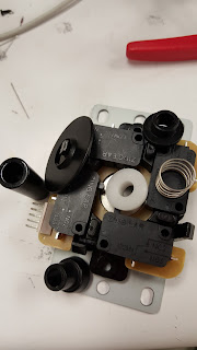
The Hori Silent Optical Hayabusa joystick shown on the left with it's cover off is just different enough to make things complicated. It's restrictor gate on the right has latches and mounting holes that are different enough that swapping gates out is complicated.

It isn't however impossible, because there is sort of a quick destructo-modification that you can do to put the Kowal gate, but it requires destroying the original gate and at the time of this post there isn't a way to purchase a backup if you super ruin the original. Overall that sounds like a bad idea.

I also don't really know how effective the destructo-mod is so I'm reluctant to attempt it until there's a better fall back plan. I did think it was kind of interesting upon finding this out, my initial thought was... well, I suppose I could try to CNC something out of aluminum or polycarbonate. If no one comes out with a better solution, I will come back to this to idea, but currently I'm working on some more interesting projects. So I expect to have some more quality posts here in the new future. The summer has not been completely wasted.

Tuesday, February 23, 2016

MadCatz Alpha FightStick Modification Process

For the most part, getting the MadCatz Alpha FightStick modified was pretty straight forward with a few exceptions. I was able to successfully switch out all stock components with Sanwa parts like I had originally planned, but I'd like to go through how I did it and point out some of the issues I ran into.

In the previous blog post, I covered taking the Alpha apart and planning a little so I'm going to overlap just a bit for continuity.

gross

The guts. I needed to get all the buttons and the joystick out because they were all mashed potato feeling. Beware, the molex connectors are not easy to unclip and I broke a corner of the plastic housing on one connector trying to remove the cable. All I'm saying is just be gentle and take it slow when prying each connector out. Unclipping all the ribbon cables and removing the PCB makes it much easier to access all of them.
 

Components and everything everywhere. Super grease.
Stock Joystick

Too strong to separate.Removing the joystick should be the first step after you removed the PCB and ribbon cables. It helps keep all of that wire mess out of your working space. The stock joystick, whatever it is, was kind of interesting to remove. My initial approach would normally be to unscrew the balltop from the shaft and then remove the joystick from the chassis, but no matter how hard I tried I could not remove the ball top from the shaft. I mean the balltop is screwed on with Loctite or some other method of fusing the plastic ball to the shaft was used because I could not separate them. So I needed to remove the e-clip which can slide out from on top of the black plastic actuator. Once the e-clip is removed, the shaft with the balltop falls out and the rest of the joystick can be removed.
Here's a quick comparison of the stock joystick compared to a Sanwa JLF. There doesn't appear to be much difference and for the most part the feeling wasn't terribly different, but I did get an air of satisfaction knowing I was using the Sanwa JLF joystick(confirmation bias?). The Sanwa JLF is on the left and the stock joystick is on the right.
Look very similar.
Sanwa JLF and Alpha Stock Joystick


Buttons so short you'll flip.

After that is settled, moving to the buttons was pretty straight forward. Desolder, take out the button, put in new button, solder, and check continuity. Because, I didn't want to memorize which color went to which input on the PCB, I just swapped out a single button at a time. Since buttons, or equivalently switches, have no polarity preference you can solder the ground wire and signal wire on either side as long as you don't short the two together. It helps to stay consistent for troubleshooting later though, thankfully I didn't have to.

The buttons have a single signal wire running from one side and then the ground signal is daisy chained to the rest of the buttons. It was kind of troublesome soldering two and three wires to a single post, lots of hot finger soldering owies.


Here's a photo comparing the Sanwa buttons with the Alpha stock buttons. There is a height disparity that later on marginally effects how the PCB mounts to the chassis. The Sanwa button is on the right and the stock button is beneath the wires, but on the left.
short tall
Sanwa and Alpha Stock Button Comparison


Look at that not so great USB solder job. It passes, but I should have gone in and cleaned it up.
Once all of the new buttons were soldered in I just needed to remount the PCB, close it up, and call it done-zo. However, as I mentioned earlier, because the Sanwa buttons are taller than the stock buttons that come in the Alpha this causes mounting issues with the PCB. The PCB is supposed to sit above the buttons, and there wasn't a whole lot of clearance beneath it so when mounting it back up it is not wise to screw down those tiny bolts as tight as possible. I'm sure the PCB can handle it, but when I see fiber glass beginning to bend it always makes me nervous.
These photos are the best I could do with my camera phone to get a profile shot of how the PCB sits on top of the new Sanwa buttons. It's passable. The PCB clears the buttons in terms of critical fitting and the only consideration that needs to be made is just lightly tightening the PCB until it stops wiggling, but before the PCB starts to bend from pressure.


Put it all back together like a sandwich that you can't eat that's made of plastic, bolts, fiberglass, and lead and you get the Alpha fightstick with brand new shiny parts.  Overall, I'm pretty happy with how it turned out and also how it has improved how it feels now. Second player better be thankful that I cared enough to do this instead of giving them the pleb controller.
Nice new pink things.
Finished

4/15/2018 Update:
A user in the comments (Manu Der Fuchs) asked if it was possible to take some more photos of the internals of the Alpha fightstick. The main interest was to see what kinds of buttons were used for the L1/L2 buttons. I suspected that they were push buttons and that you could wire/solder the more conventional arcade style buttons in place. So here are the photos of the internals:


The upper PCB is where all the button circuitry for the top of the fightstick is placed. Just a few phillips screws are in the way of getting access. Pretty simple.


These two photos show the main board after it's been unscrewed down. The photo on the right shows the two left most push buttons are the L2 and L1 buttons with the far left being L2 and the second from the far left being L1. It should be simple enough to solder wires to the sides of push buttons without having to remove anything, but if you wanted to be really thorough you would use a multimeter in continuity checker mode and figure out which ways the buttons are oriented. I don't have any of my tools with me to give you the answer, but I can probably do that later if there's interest.  I hope this helps.

Thursday, January 29, 2015

Making A Model M SSK

 In July 2013 I realized that every keyboard that I owned was scrub level and wanted to do something about it. Naturally, I went for overkill and  found that I had three IBM Model M keyboards with not enough desk space. After falling in love with all things mechanical keyboards with a preference for the buckling spring I did all sorts of searching for home made modifications and other versions of the Model M.


I found out about a model that IBM made specifically to save desk space called the Model M SSK. Unfortunately, these keyboards were not as popular as their full sized brother and were not in production very long. As a consequence of this, the keyboard is difficult to acquire and usually sells on eBay for upwards of $200. Instead of saving to buy one of these, I decided to make one using one of the three full sized keyboards I already had.

Thankfully, or rather unfortunately, one the keyboards I had was a "rubber dome" version of the Model M defeating the entire purpose of the keyboard so I didn't feel terrible potentially destroying it. The biggest part of the project was learning how to "Nut and Bolt Mod" and finding the tools I needed to get it done.

It's blasphemy that IBM even made a rubber dome version.
This, clearly, is the fully disassembled keyboard and you can see that the keyboard is rather simple. It's a steel plate, plastic housing for springs, and a three layer plastic trace for each key.

The goal at this point was to successfully bolt modify the keyboard and then move forward with removing the number pad section of the keyboard to imitate the SSK.


Drilling holes where there used to be fasteners.
Here are just some of the various stages of the project. In order to bolt modify the plastic housing drilling through holes was necessary to replace the molded plastic fasteners. I think there were somewhere around 25 to 30 drilled holes.

Cutting the steel back would have been incredibly difficult otherwise.


The second stage was cutting the steel plate that is used as the foundation of the keyboard to the correct length such that I could remove the number pad.


I tried to keep as much of the case in tact as I could.
The third stage of keyboard destruction was trying to get cut the case so that I could keep as much of the edges so that the keyboard looked seamless.
The final stage of the whole bolt modification process was reassembling everything together so that it would be sturdy once everything was put in place. I used a rubber cement epoxy and some vinyl house siding to help the separate case pieces stick together better. The clamps always help.


Once everything was cut up and properly fitted, the rest was just to fold over the switch membrane underneath itself and fix it all up. Here are some remaining photos that I kind of liked that sort of debut the rebirth of my keyboard-stein.


Here is the keyboard comparison to the full sized and the SSK that I created on the bottom. At this point I didn't have keys just yet because I hadn't ordered replacements. The ones that originally came with the rubber dome Model M were solid with no place for the spring to fit into.


Here is the completed project and I still use this keyboard now, not that should be any surprise. I do love my keyboards. The only thing that I'm upset with about this project is the seam that can be seen at the top of the keyboard above the scroll lock key. It just takes away from the beige magnificence.