 |
| The Beginning of a Big Pain |
The amplifier schematics and everything for the Bijou used to be hosted on the Cavalli Audio website. Unfortunately, sometime between last May and now, the site is mostly an empty page. If you're interested in this project, I think you should leave a message with Cavalli Audio on their contact page asking them to re-host the information. I am still awaiting a response. In the mean time, you can use something called the Wayback Machine to check out a majority of information that they once had.
EDIT(March 25, 2016): I don't know if many others tried contacting Cavalli Audio, but they did re-host their project on the Bijou so now all the old information is there for everyone interesting in building their own Output Transformer Less(OTL) Bijou headphone amplifier. Thanks to everyone that contacted Cavalli and thanks to Cavalli for listening.
Anyways, even though this kit is probably somewhere between intermediate and advanced difficulty to complete, I wanted to up the ante. The kit does not come with an enclosure for everything, so this is where I would decide that I should do something interesting and ultimately a gigantic pain to deal with. I've seen many other people put this amp in nice aluminum boxes or wood cases that they either made themselves or paid for and I mean no disrespect because they always look great. So what did I do? I decided to put the Bijou in a toaster. To be more specific, I used a four slicer toaster.
I believe I could have finished in maybe a month or so without having to work more than just a couple weekends and on my spare time. Instead, I worked on it for three months and stopped when I got to a complicated mounting situation that I did not have a good idea on how to solve. I decided to finish it because my friend Kyle Woodworth had inspired me with his new blog and here is the start to finish process with, I'm very happy to say, decent success.
I'm going to mostly gloss over the detail on assembling the PCB's with their components. I think pictures speak a little louder in this case and I don't want to focus on the soldering nearly as much because this was not the challenging aspect of the project.
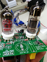 |
| Debut of Tubes |
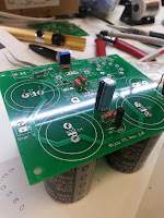 |
| Partial Assembly |
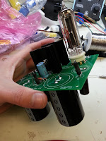 |
| Assembly of the Power Supply |
For some guidance, the PCBs are labeled well so the best instruction here is truly following the parts list and just doing a check list to make sure everything is where it should be. Also, as a note of caution, I have seen others mount the heatsinks and mosfets underneath the power supply board(it's the middle board in the bottom photo) and I do not believe that's wise. The heatsinks would then sit right on top of some traces and could potentially burn them to bits. I did not test this, so I could very well be worrying too much about it, but I did not want to find out after completion that my power supply traces were burning off.
 |
| Full Assembly of the Bijou |
A new aspect I did not have much experience with before the Bijou was messing with transformers. I understand how they work on a circuit schematic level, but I had never used one in a project or wired one up myself. So that was interesting and a little scary because the transformer being used is the 370DAX made by Hammond Manufacturing and it pumps out two lines of 260VAC and quite frankly I did not want to find out how tingly that feels.
 |
| Testing the Power Supply Board |
I would consider this setup super not safe. Sure, everything is insulated, but what you don't see is that I have floated ground and have nothing running to the third prong in the event of a short.
Word to the wise( or maybe the unwise), it takes an awfully long time for the output to drop to a "safer" level of voltage even after it's been unplugged.
Enter the Toaster.
 |
| Bella Toaster |
This may have been the poorest choice of toasters in my personal opinion, but I also did not do much research on toasters after the fact to see how much better or worse other options could have been. I think I may be mostly angry at how much of a pain it was. It is probably safe to assume any toaster would have caused me an equal amount of grief.
This particular one was chosen because I left it up to a vote for the instrument room staff at the time and this was the winner. (Maybe the lesson is don't let others vote on what you're going to be working on?)
After this project, it is my firm belief that toasters should only have bread and bread related things inside them. It is a strictly breakfast food device.
 |
| Top Cover Taken Off |
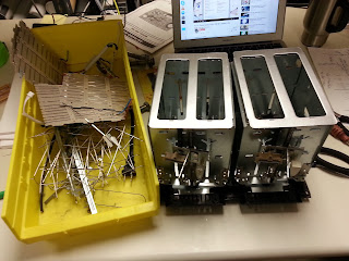 |
| Gut Removal |
This toaster had some really strange triangle shaped screws that needed to be removed to get the cover off. Maybe I should have taken that as the first sign that maybe the manufacturers don't want me taking apart their toasters to put tube amplifiers inside them.
This is where the biggest obstacles start coming into play. Where do I put the hefty transformer so it can stay hidden? How do I mount the Bijou PCBs inside the bread slot area? The goal was to make it so the tubes stuck out of the bread slots. And I know what you're thinking, will the toaster handles raise and lower the tubes? No, maybe in a future project with more toaster planning. Will it still make toast? Maybe, it does it get warm. Then what good is having your amp in the toaster if it doesn't make toast? Yes, you're now starting to see where my pain begins. In all honesty though, I have never seen an amplifier enclosed inside of a toaster and thought that novelty outweighed something more.. "practical" (boring).
 |
| Cut Up Bread Slots |
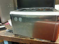
I decided to "hide" the transformer in the direct center of the toaster which required me to remove some of the inside material to make room for it. Another toaster fact, because the base was made entirely out of plastic and the transformer needed to sit on something didn't bend under it's weight, a 1/16 inch aluminum plate was mounted to the base for support which also served as a grounding plate later on.
 |
| Knockout holes for Left and Right Channels |
Knockout punches were used to put holes in the toaster chassis for the Right and Left channel audio inputs and quarter inch headphone jack.
I also wanted to include a power entry module that used a fuse in the event that something shorted, but my grounds weren't properly tied to each other, and would pull enough amperage to blow the fuse before it blew me away.
 |
| Quarter Inch Headphone Jack |
 |
| Mounted L/R Channels and Power |
This is where I stopped because I knew the next step would be making a mounting solution and then wiring the mess together.
This is where Kyle inspired me to spend all of Saturday and Sunday of spring break getting this project restarted with the goal of finishing. Thank you Kyle. Some people just need a little push to get things started, others need help finishing things, and there is myself. Honestly though, I'm truly thankful that this is finished and I have some interesting content to provide to others.
I started by making custom bent brackets from 1/16 inch aluminum for the Left and Right channel PCBs. These were the easier of the two mounting solutions because the amplifier PCB did not have large objects underneath that I needed to avoid so I could run parallel bars and mount each board in their respective spot. Unfortunately, not everything was smooth, the boards were a very tight fit and were in contact on the edges with each other. These boards do not have a ground plane implemented and I was concerned that because I have AC running to each board for heating the vacuum tubes I should have them at least separated. So what is someone to do when PCBs mounted next to each other are touching and they shouldn't be? Why, you shave the PCBs of course. Not having a ground plane made this a lot easier and worked like a charm.
 |
| Custom Bent Brackets |
 |
| My Woes |
 |
| L/R Channels Mounted |
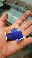
For both mounting solutions, I needed to bend aluminum, but the power supply board had huge capacitors mounted underneath and it had heatsinks mounted on top so the whole board had to sit lower closer to the transformer so I could not run parallel bars without cutting some fancy shapes out which would have been much more complicated than I wanted to deal with. So I just made four custom angle brackets.
 |
| Custom Angle Brackets |
 |
| All Boards Mounted |
 |
| More Woes |
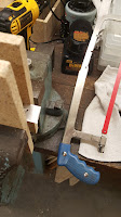
Naturally, all but one of the brackets needed to be "modified"(with a hacksaw) because of various things that I did not take into consideration when planning out how to mount the power supply board. The biggest complication was that I could not physically see anything underneath the board with it all in place, but everything went according to plan if we assume my plan was to get it mounted and not to get it mounted easily.
The next step now is to obviously wire everything. However, that means unmounting everything and connection wires to the boards first and then string the wires around the chassis because wires don't pass through physical objects to make your life easier(feel free to quote me on that). I know I'm going to show you five photos of various points in the wiring procedure, but this honestly took several hours to do and I was just trying to finish. I didn't take any more time to make it look absolutely spectacular, just enough to get it to work and be presentable.
 |
| Put Back Together |
Putting Humpty Dumpty back together again took a special finesse that can only be summed up as pushing wires out of the way of holes where screws would go and being gentle to not tug wires out of their screw down terminals.
 |
| Humpty Dumpty Equipped with Tubes |
Now with everything assembled this does look pretty good. Turning it on almost seems to be a shame if it doesn't work. Don't worry, it works and it looks fantastic.
 |
| Front View of the Bijou-Toast Amp |
 |
| Bijou-Toast Amplifier On and Operational |
I recorded a small video where I wasn't paying attention to what I was saying at the time while I was recording so you hear me talking a little. Also, it's another vertical video, I'm really sorry, I will try to remember to do better.
This was a very interesting project; I'm much happier now that it successfully turned on, didn't short out, didn't shock me, made sounds, and is completed(ish). My recommendation is put it in a box instead of a toaster.
*EDIT (July 10, 2016): Turns out the amp works really well. It happens that I should not plug the 1/4" jack all the way in. I had to leave maybe an 1/8" sticking out at the base and both channels kicked in and sound pretty good. I don't know why it took me so long to check it. I guess I was a little discouraged at first. Long story short, everything works and it's wonderful.


