In the previous blog post, I covered taking the Alpha apart and planning a little so I'm going to overlap just a bit for continuity.
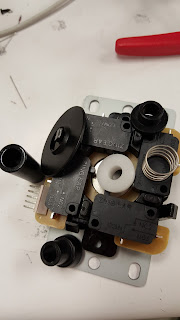
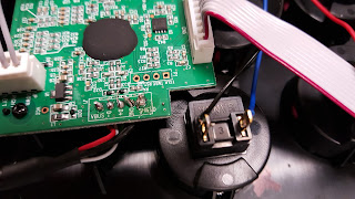
The guts. I needed to get all the buttons and the joystick out because they were all mashed potato feeling. Beware, the molex connectors are not easy to unclip and I broke a corner of the plastic housing on one connector trying to remove the cable. All I'm saying is just be gentle and take it slow when prying each connector out. Unclipping all the ribbon cables and removing the PCB makes it much easier to access all of them.
 | |
| Stock Joystick |
 Removing the joystick should be the first step after you removed the PCB and ribbon cables. It helps keep all of that wire mess out of your working space. The stock joystick, whatever it is, was kind of interesting to remove. My initial approach would normally be to unscrew the balltop from the shaft and then remove the joystick from the chassis, but no matter how hard I tried I could not remove the ball top from the shaft. I mean the balltop is screwed on with Loctite or some other method of fusing the plastic ball to the shaft was used because I could not separate them. So I needed to remove the e-clip which can slide out from on top of the black plastic actuator. Once the e-clip is removed, the shaft with the balltop falls out and the rest of the joystick can be removed.
 |
| Sanwa JLF and Alpha Stock Joystick |
After that is settled, moving to the buttons was pretty straight forward. Desolder, take out the button, put in new button, solder, and check continuity. Because, I didn't want to memorize which color went to which input on the PCB, I just swapped out a single button at a time. Since buttons, or equivalently switches, have no polarity preference you can solder the ground wire and signal wire on either side as long as you don't short the two together. It helps to stay consistent for troubleshooting later though, thankfully I didn't have to.
The buttons have a single signal wire running from one side and then the ground signal is daisy chained to the rest of the buttons. It was kind of troublesome soldering two and three wires to a single post, lots of hot finger soldering owies.
Here's a photo comparing the Sanwa buttons with the Alpha stock buttons. There is a height disparity that later on marginally effects how the PCB mounts to the chassis. The Sanwa button is on the right and the stock button is beneath the wires, but on the left.
 |
| Sanwa and Alpha Stock Button Comparison |
Once all of the new buttons were soldered in I just needed to remount the PCB, close it up, and call it done-zo. However, as I mentioned earlier, because the Sanwa buttons are taller than the stock buttons that come in the Alpha this causes mounting issues with the PCB. The PCB is supposed to sit above the buttons, and there wasn't a whole lot of clearance beneath it so when mounting it back up it is not wise to screw down those tiny bolts as tight as possible. I'm sure the PCB can handle it, but when I see fiber glass beginning to bend it always makes me nervous.
These photos are the best I could do with my camera phone to get a profile shot of how the PCB sits on top of the new Sanwa buttons. It's passable. The PCB clears the buttons in terms of critical fitting and the only consideration that needs to be made is just lightly tightening the PCB until it stops wiggling, but before the PCB starts to bend from pressure.
Put it all back together like a sandwich that you can't eat that's made of plastic, bolts, fiberglass, and lead and you get the Alpha fightstick with brand new shiny parts. Overall, I'm pretty happy with how it turned out and also how it has improved how it feels now. Second player better be thankful that I cared enough to do this instead of giving them the pleb controller.
 |
| Finished |
4/15/2018 Update:
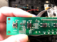
A user in the comments (Manu Der Fuchs) asked if it was possible to take some more photos of the internals of the Alpha fightstick. The main interest was to see what kinds of buttons were used for the L1/L2 buttons. I suspected that they were push buttons and that you could wire/solder the more conventional arcade style buttons in place. So here are the photos of the internals:
The upper PCB is where all the button circuitry for the top of the fightstick is placed. Just a few phillips screws are in the way of getting access. Pretty simple.
These two photos show the main board after it's been unscrewed down. The photo on the right shows the two left most push buttons are the L2 and L1 buttons with the far left being L2 and the second from the far left being L1. It should be simple enough to solder wires to the sides of push buttons without having to remove anything, but if you wanted to be really thorough you would use a multimeter in continuity checker mode and figure out which ways the buttons are oriented. I don't have any of my tools with me to give you the answer, but I can probably do that later if there's interest. I hope this helps.


Nice work! I am thinking of getting one of these as my first mod.
ReplyDeleteIt's not a bad little unit to mod, but having used it I'm a little hesitant to recommend it. Modifying it is nice and simple, but using it can be challenging unless you use it on a flat surface because it likes to move on you in your lap. It almost needs to be mounted to a lap board or something. Anyways it's super nice for modifying, but it can be a pain to use unless you are at a desk.
DeleteVery nice mod! Do you happen to have images from the top panel board with the L1/L2 Buttons? I made an 8-Button Fight Stick that I want to use with the hardware from the alpha stick and am not sure if its possible use Buttons for L1/L2.
ReplyDeleteL1/L2 are the square push buttons near the top correct? I don’t have the ability to take a photo of it until this weekend because it’s not at my house so I can get back to you then.
DeleteHowever, it should be possible to do. Those buttons are just really tough push buttons you could either cut their wire and connect your Sanwa buttons directly or perhaps even follow it back to the PCB. So I suspect it’s possible, but I’ll try to get back to you with some evidence once I can.
Much appreciated! My alpha stick arrived in the meantime and I temporarily soldered the L1/L2 wires directly to the button legs. I'm glad the PCB is so easy modifiable. Anyways, your blogpost was a help getting it done, thanks for sharing your experience with us.
DeleteAbsolutely! I’m glad I could help:)
DeleteI wanted follow up with an update. I haven’t forgotten to take photos, I just managed to be busy the entire weekend so unfortunately I won’t be able to take things apart for at least two weeks. I do have it in my calendar set to remind me. I move rather slowly on personal projects during the semester.
DeleteI made a small update with some photos. Hopefully this helps. If there are any questions let me know.
DeleteHi, great article! I was wondering if there was space to mount two additional buttons under buttons X and O if you would be able to rewire them to L1 and L2. Maybe low profile buttons would fit. I can't tell from the pics if the pcb is right under the buttons.
ReplyDeleteI think if you’re trying to run wires to the X and O buttons then it should be possible without doing anything special. L1/L2 are kind of special since the button that you push down on isn’t actually a push button with wires attached to the plastic. L1/L2 are buttons basically wired through PCB, if you wanted to rewire these you’ll either have to do a fly wire job or need to replace the PCB inside the stick. At least that’s the way I understand your question, hope that helps.
DeleteWow I'm a little late but this was very helpful I'm actually trying to make the most portable silent stick so I was thinking of putting a UFB in there but those top row buttons I want to still use them any advice to wire them to the new pcb
ReplyDelete
DeleteI believe that the top row (I’m assuming you’re referring to the Lock, start, select, etc.) were actually just simple push buttons soldered directly to the PCB of the alpha.
You may be able to run wires and directly solder to the push buttons and connect them to the correct universal fight board inputs. It may require cutting the original Alpha PCB to make room for the UFB, but unfortunately it’s been some time since I’ve looking at the Alpha’s guts. Let me know what you find, I may have to investigate more with you.
This comment has been removed by the author.
ReplyDelete