Showing posts with label fightstick. Show all posts

Saturday, July 9, 2016

Hori Hayabusa and Hayabusa Silent Optical Joysticks

I was debating about even making a post about this because for some reason I felt like that this isn't entirely engineering related, but on the other hand it's also one of my hobbies. So let me lay out some of the details and we can see if this is useful to anyone else.

About four months ago(I think, I can't remember exactly) I purchased a Hori Hayabusa joystick and it works pretty well. It's somewhere inline with the JLF. This isn't really a review of the joystick. Anyways, a wonderful person known as Kowal through Shoryuken forums came up with a fantastic octagonal restrictor gate.

What a wonderful octopus
Hori Hayabusa Original w/ Kowal Octo Gate


This is what the original Hayabusa looks like with the restrictor gate removed. I'm holding up the Kowal octagonal gate right above it. There's nothing entirely too special about it other than it's just something different than the very commonly used Sanwa JLF joystick.

However, I'm posting it to bring attention to the fact that the silent optical Hayabusa is... ehh.. I don't want to say significantly different, but it is different enough to prevent swapping restrictor gates.


annoyingly differentno clicky clicky
The Hori Silent Optical Hayabusa joystick shown on the left with it's cover off is just different enough to make things complicated. It's restrictor gate on the right has latches and mounting holes that are different enough that swapping gates out is complicated.

It isn't however impossible, because there is sort of a quick destructo-modification that you can do to put the Kowal gate, but it requires destroying the original gate and at the time of this post there isn't a way to purchase a backup if you super ruin the original. Overall that sounds like a bad idea.

I also don't really know how effective the destructo-mod is so I'm reluctant to attempt it until there's a better fall back plan. I did think it was kind of interesting upon finding this out, my initial thought was... well, I suppose I could try to CNC something out of aluminum or polycarbonate. If no one comes out with a better solution, I will come back to this to idea, but currently I'm working on some more interesting projects. So I expect to have some more quality posts here in the new future. The summer has not been completely wasted.

Tuesday, February 23, 2016

MadCatz Alpha FightStick Modification Process

For the most part, getting the MadCatz Alpha FightStick modified was pretty straight forward with a few exceptions. I was able to successfully switch out all stock components with Sanwa parts like I had originally planned, but I'd like to go through how I did it and point out some of the issues I ran into.

In the previous blog post, I covered taking the Alpha apart and planning a little so I'm going to overlap just a bit for continuity.

gross

The guts. I needed to get all the buttons and the joystick out because they were all mashed potato feeling. Beware, the molex connectors are not easy to unclip and I broke a corner of the plastic housing on one connector trying to remove the cable. All I'm saying is just be gentle and take it slow when prying each connector out. Unclipping all the ribbon cables and removing the PCB makes it much easier to access all of them.
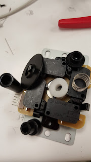
 

Components and everything everywhere. Super grease.
Stock Joystick

Too strong to separate.Removing the joystick should be the first step after you removed the PCB and ribbon cables. It helps keep all of that wire mess out of your working space. The stock joystick, whatever it is, was kind of interesting to remove. My initial approach would normally be to unscrew the balltop from the shaft and then remove the joystick from the chassis, but no matter how hard I tried I could not remove the ball top from the shaft. I mean the balltop is screwed on with Loctite or some other method of fusing the plastic ball to the shaft was used because I could not separate them. So I needed to remove the e-clip which can slide out from on top of the black plastic actuator. Once the e-clip is removed, the shaft with the balltop falls out and the rest of the joystick can be removed.
Here's a quick comparison of the stock joystick compared to a Sanwa JLF. There doesn't appear to be much difference and for the most part the feeling wasn't terribly different, but I did get an air of satisfaction knowing I was using the Sanwa JLF joystick(confirmation bias?). The Sanwa JLF is on the left and the stock joystick is on the right.
Look very similar.
Sanwa JLF and Alpha Stock Joystick


Buttons so short you'll flip.

After that is settled, moving to the buttons was pretty straight forward. Desolder, take out the button, put in new button, solder, and check continuity. Because, I didn't want to memorize which color went to which input on the PCB, I just swapped out a single button at a time. Since buttons, or equivalently switches, have no polarity preference you can solder the ground wire and signal wire on either side as long as you don't short the two together. It helps to stay consistent for troubleshooting later though, thankfully I didn't have to.

The buttons have a single signal wire running from one side and then the ground signal is daisy chained to the rest of the buttons. It was kind of troublesome soldering two and three wires to a single post, lots of hot finger soldering owies.


Here's a photo comparing the Sanwa buttons with the Alpha stock buttons. There is a height disparity that later on marginally effects how the PCB mounts to the chassis. The Sanwa button is on the right and the stock button is beneath the wires, but on the left.
short tall
Sanwa and Alpha Stock Button Comparison


Look at that not so great USB solder job. It passes, but I should have gone in and cleaned it up.
Once all of the new buttons were soldered in I just needed to remount the PCB, close it up, and call it done-zo. However, as I mentioned earlier, because the Sanwa buttons are taller than the stock buttons that come in the Alpha this causes mounting issues with the PCB. The PCB is supposed to sit above the buttons, and there wasn't a whole lot of clearance beneath it so when mounting it back up it is not wise to screw down those tiny bolts as tight as possible. I'm sure the PCB can handle it, but when I see fiber glass beginning to bend it always makes me nervous.
These photos are the best I could do with my camera phone to get a profile shot of how the PCB sits on top of the new Sanwa buttons. It's passable. The PCB clears the buttons in terms of critical fitting and the only consideration that needs to be made is just lightly tightening the PCB until it stops wiggling, but before the PCB starts to bend from pressure.


Put it all back together like a sandwich that you can't eat that's made of plastic, bolts, fiberglass, and lead and you get the Alpha fightstick with brand new shiny parts.  Overall, I'm pretty happy with how it turned out and also how it has improved how it feels now. Second player better be thankful that I cared enough to do this instead of giving them the pleb controller.
Nice new pink things.
Finished

4/15/2018 Update:
A user in the comments (Manu Der Fuchs) asked if it was possible to take some more photos of the internals of the Alpha fightstick. The main interest was to see what kinds of buttons were used for the L1/L2 buttons. I suspected that they were push buttons and that you could wire/solder the more conventional arcade style buttons in place. So here are the photos of the internals:


The upper PCB is where all the button circuitry for the top of the fightstick is placed. Just a few phillips screws are in the way of getting access. Pretty simple.


These two photos show the main board after it's been unscrewed down. The photo on the right shows the two left most push buttons are the L2 and L1 buttons with the far left being L2 and the second from the far left being L1. It should be simple enough to solder wires to the sides of push buttons without having to remove anything, but if you wanted to be really thorough you would use a multimeter in continuity checker mode and figure out which ways the buttons are oriented. I don't have any of my tools with me to give you the answer, but I can probably do that later if there's interest.  I hope this helps.

Tuesday, August 4, 2015

Custom Built Fightstick using Arduino Uno

As I was going through all of my collected fightstick parts, it occurred to me that I have all but one component to build myself a second fightstick. I just needed the JLF Sanwa joystick and a box to put all of it in. What really sent me over the edge was when I found a controller box that was being thrown out.


I'm not entirely sure what it was originally, but it had a bunch of old controller parts probably for something audio/video related. So naturally, it needed to be destroyed.


Here's a better photo of it after I removed all the old knobs and switches. The tricky part about using this as the fightstick box was figuring out a way to overlay a new piece of metal so that I could place new holes for all the buttons and joystick. There were too many spaced out holes to save the original piece and the faceplate has two bends on the top and bottom at different heights. Later you'll see a photo better explaining what I mean.


I knew the idea that I wanted to go with, but I needed some help from some machinists that work in the dark depths of the Electrical Engineering building. Joe Beeler and Ricky Cardenas, two very talented machinists that made this much easier to put my thoughts into something that could physically be worked.

They cut out the top part of the place leaving the two bends at the bottom so we didn't need to warp aluminum to recreate the original.


They helped size and cut a new piece of aluminum so that we could make a new faceplate. Using a layout that I found at slagcoin  we used radio chassis punches to make perfect holes that would house the buttons and the joystick.

I was incredibly impressed with how well the punches worked. They were very simple to use as well, if not for the punches we would have had to use the CNC to cut the holes.


Here are two angles of the fightstick before all the wiring went into it. We added two buttons on the right of the box to include a start and select button.


I don't have any photos of programming the Arduino Uno because it wouldn't really explain much. Anyways I used some helpful links and sources from the UnoJoy github from Alan Chatham. He did a pretty decent job providing information on how to get the Arduino to be a useful joystick controller. I did however make some changes to the code, however because I was not using any analog joystick inputs and I wanted to map only six buttons for the fightstick.


Here is the Arduino Sample Code
// Changed from
// controllerData.l1On = !digitalRead(10);
controllerData.r2On = !digitalRead(10);

//Commented out all of the analog inputs since I didn't use any of them
// controllerData.leftStickX = 128;
// controllerData.leftStickY = 128;
// controllerData.rightStickX = 128;
// controllerData.rightStickY = 128;


I'm not going to post a tutorial on what steps I did because the GitHub readme file does a pretty decent job at explaining what steps are necessary, but if there are questions I don't mind making some help posts.


Here's the very quick and dirty wiring job. It was 11 pm at this point and I just wanted to finish it and test it. I was a little upset that I soldered directly to each button, but at this point in the project I realized that I only spent a total of $25 for the entire project and didn't want to spend more just to challenge myself to see how cheaply I could make it.

I'm sure I'll go in on this later and replace the soldered wire with something more modular, but for the time being I'm incredibly happy with how this works.


Here's a little photo showing that the fightstick worked on my Playstation 3. Later I tested it on PC successfully. I'm testing on Guilty Gear Xrd in the photo if anyone was interested.


This is Joe Beeler(left) and Ricky Cardenas(right). They were embarrassed I was taking their photo, but these guys were very helpful and without their machinist knowledge I believe that this project would have been much more overwhelming. So this is a big thank you to them.

Also thank you to Alan Chatham for doing a lot of work on the UnoJoy project.

Friday, March 27, 2015

Optical Sensor installed in Qanba Q4 Fightstick

A hobby of mine is to use small arcade style controllers to play fighting games. I'm pretty decent. Anyways, I recently found that an optical sensor existed that could replace the microswitches in the joystick. The microswitches act as a mechanical sensor that detects movement on the joystick (up, down, left, right, and the corner combinations). These are all well and good, but having a silent joystick that is slightly more precise is more my style. The only complication is that the special optical sensor required a power source and while I could have soldered something directly to the circuity inside my Qanba Q4, I wanted the option to switch between the optical sensors and the microswitches without having to solder and unsolder every time between the two.

So I designed a little pcb that would facilitate as a USB to power hub. The intention was to make the cord modular from the fightstick so instead of having an always connected power cable, the cable could be removed completely. Also, the power for the Qanba pcb and the optical sensor would connect to my pcb and could be disconnected when switching from optical to microswitches.


So this is the board. Super small, super simple. Sadly, I was not able to use it. Not because it didn't work, but because I did not have the proper connectors to attach to the Qanba pcb. Dupont cables didn't work, molex didn't work, and the do-it-yourself wire connectors that are in the instrument room here at Purdue didn't work either.

I'm under the impression that the wire connectors that Qanba uses are special or at the very least not very common. While iteration ALPHA didn't work, I plan to go back with iteration BETA to hopefully use my design, but because I wanted to use the sensor last night I had to improvise.


I'm not sure if anyone knows the name for these particular connectors, but if you do please email me because I don't know what to search for.

Also because I was really annoyed that every photo of the Qanba Q4 pcb was taken by a potato, here is a better photo of it with no modifications and I've unhooked the microswitches along with the power connector from the USB cable.


Here is my improvised cable soldering. I was really hoping to avoid soldering so that I could keep it simple for others to implement, but c'est la vie.

It's kind of a bad photo, but the main points to take from it is that I'm pulling 5 volts (red) and ground (black) from the USB power cable. The other four colors are direction inputs for the Qanba pcb.


So here is the final connection scheme. I recycled the Sanwa microswitch cable that was already being used with my JLF stick (the joystick itself) for the directional inputs, and the important part is that you can see that the power and ground connectors are soldered to the USB power cable.

Everything worked out a lot better than expected after I already gave up on finding a proper connector at 11:30 pm. Minimal soldering and the optical sensor works very well. I don't expect there to be any questions, but if you're looking at this in the future four years from the date of this post or something like that, feel free to send me an email. I'll probably respond unless the internet stops being a thing in the future.