Sunday, August 7, 2016

iMac 21.5" mid 2011 CPU Upgrade and Repair

At the end of March while the school semester was still in gear, I managed to come across a particular broken iMac at Purdue Salvage. It had a broken glass screen, no hard drive, no RAM, but it was 2011 and it was only going for $100. Against some better judgement, I decided that buying it and repairing it would be kind of fun since I had never actually taken apart an Apple product and I later confirmed that upgrading components was a possibility.

I don't think you can see it very well, but there's a massive crack in the glass that spans the entirety of the screen. I didn't know this until after I took one of these apart that the glass portion of the screen is actually held on to it by some strong magnets. It was really easy to replace and (compared to buying a new iMac all together) was inexpensive to replace. It kind of makes you wonder why they decided to junk the computer.

Purdue Salvage, or the people that handed over to be tossed, decided that removing the hard drive and RAM would be a smart idea then scrapped the whole unit. So the entire process was sort of concerning because I could not confirm if there were other problems with the iMac itself, but I did the initial test of just starting it up and getting the three long(and really loud) beeps that indicated "RAM IS MISSING OR MAYBE HARDWARE IS NOT ACCEPTABLE"
Cascaaaaa
Initially I wanted to install a SSD into it rather than a HDD because it was already kind of an older unit and came stock with a core i5 processor so it could use the extra speed boost. I figured since I was trying to get it up and running again I would figure out if I could drop an i7 into it while I was taking it apart.

As it happens there are a number of different sites and probably dedicated people that have determined what kinds of processors (and probably other components) that can be swapped out of certain models of Apple computer products. Turns out, theory suggested that a core i7 could replace this model of iMac. I was still kind of hesitant however, because Apple does provide an i7 2600S processor which is a low power version of the processor, but they don't mention anything about the "full" version of the i7 2600 processor. Through my power of sleuthing and the internet I was able to find posts from people that allegedly replaced their processors with the standard core i7 2600 cpu, but no one showed any screenshots of this proving one way or the other. Come on internet, provide proof of these sorts of things. How else could you be trusted?


|_?_|
 This was a pretty good sign. I tried using Other World Computing's HDD to SSD upgrade kit for my model of iMac. Unfortunately, I ran into some different problems. So, you can't use the Snow Leopard disk to install OSX because support for SSD wasn't available. Well that's okay, I have a Macbook Air with El Capitan and created an install USB drive with it. Try again, well, it managed to get past boot up and I was able to get to disk utility, but for some reason or another it managed to fail at the last portion of install. I still haven't determined why. I managed to get a lot of useful information and support from MacSales though. I spoke with someone named Bob Boldt with their sales team, not only is he awesome, but the entire staff that I've seen is incredibly helpful. I would strongly suggest that if you have any mac related issues/projects to check with them. They really do deserve it, credit where credit is due.
Disk Utility didn't really help here


As a little side note, the first time I tried to install using the OSX disk, the drive didn't want to return it to me so I had to operate to remove it.


Rauschach
 Anyways, after struggling with the SSD so long, I gave up and decided that I should just use one my left over HDD that I have sitting around with some outdated version of Linux on it. It managed to install El Capitan no problem. Hooray. I wanted to install OSX first before I opened the computer up to do cpu surgery because up to this point I didn't even know if the computer was functional. Now on to the surgery.


To harvest the organsslowly killing it
 More useful information OWC has on their website, instructional videos (that's a direct vimeo link to the video that I found useful) that step you through installing their SSD. It is a cleverly disguised video that shows you how to install one of their SSD kits, but in reality it shows you how to take out the motherboard so that you can perform serious surgery. Apple did a good job at making everything compact and fit into it's little box, but like anything that is engineered to be compact becomes really difficult to use intuition to take apart. It's a shame they don't provide the information easily to repair their units.

Time to take you apart
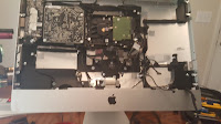
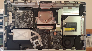
There's the meat of it. Really nice, small, and a funny shaped head. The cpu is under that square bit (the heatsink) there on the right. There's a sticker that says, "warranty void if removed", but I'm not really sure what that means. I suspect it means this screw is the important one. Once you unscrew the four screws(Torx) you get access to the cpu and the rest is like replacing any other cpu in a computer.


Warranty Voided
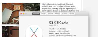
Proof is in the Puddin'Nice! Although, in my opinion they used probably way too much thermal paste on the original cpu, cleaning it up and replacing was pretty simple. Be sure to make sure that you have the orientation correct. I nearly put it in flipped(180 degrees rotated not flipped) until I reviewed some of my photos to double check. Always be thorough. Good advice to anyone for
anything... probably.

There see? Proof. You might have to look closely, but the top of the processor it says core i7 2600. Not 2600S, not core i5, it says i7 2600. It can be done. "But Steve that doesn't prove that it works." I hear you cry.

As I'm typing this post on my newly refurbished iMac, I can definitively say that the iMac 21.5" mid 2011 will accept the core i7 2600 processor and it is definitely not on fire.

3.4 Giggle Herts

I cut out the bit with the serial number. I am not sure if that's useful information to others, but if it is I probably don't want them to have it.

There it is. Core i7 2600 in an iMac that probably isn't supposed to have it in there. I haven't given up completely on the SSD, I'm going to be working on getting the SSD installed again and seeing if I can install OSX on it as the secondary drive. If that's successful, then I can make the HDD the secondary storage drive using the SSD for the main system. I also have been finding information about replacing the graphics card in this unit. Do I need it? Probably not, but I don't see why it wouldn't help or be a bad idea. This is now my little Frankintosh... ugh, that's a way better name than calling it Rorschach... why did I think of this now?

This was kind of fun, so if I figure out more information on a graphics card upgrade/replacement, I may make another blog post about it. I'll edit this post once I can get the SSD installed properly the way I want it to be. What did I learn from this? I learned that the cpu fan likes to be on all the time now and it is super loud, but that's okay because I have headphones for this sort of thing.

Saturday, July 9, 2016

Hori Hayabusa and Hayabusa Silent Optical Joysticks

I was debating about even making a post about this because for some reason I felt like that this isn't entirely engineering related, but on the other hand it's also one of my hobbies. So let me lay out some of the details and we can see if this is useful to anyone else.

About four months ago(I think, I can't remember exactly) I purchased a Hori Hayabusa joystick and it works pretty well. It's somewhere inline with the JLF. This isn't really a review of the joystick. Anyways, a wonderful person known as Kowal through Shoryuken forums came up with a fantastic octagonal restrictor gate.

What a wonderful octopus
Hori Hayabusa Original w/ Kowal Octo Gate


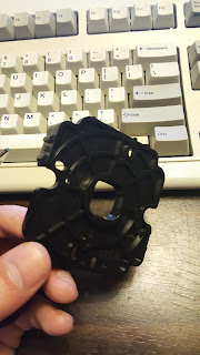
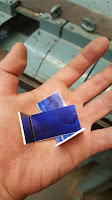
This is what the original Hayabusa looks like with the restrictor gate removed. I'm holding up the Kowal octagonal gate right above it. There's nothing entirely too special about it other than it's just something different than the very commonly used Sanwa JLF joystick.

However, I'm posting it to bring attention to the fact that the silent optical Hayabusa is... ehh.. I don't want to say significantly different, but it is different enough to prevent swapping restrictor gates.


annoyingly differentno clicky clicky
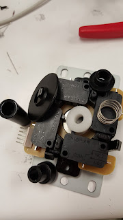
The Hori Silent Optical Hayabusa joystick shown on the left with it's cover off is just different enough to make things complicated. It's restrictor gate on the right has latches and mounting holes that are different enough that swapping gates out is complicated.

It isn't however impossible, because there is sort of a quick destructo-modification that you can do to put the Kowal gate, but it requires destroying the original gate and at the time of this post there isn't a way to purchase a backup if you super ruin the original. Overall that sounds like a bad idea.

I also don't really know how effective the destructo-mod is so I'm reluctant to attempt it until there's a better fall back plan. I did think it was kind of interesting upon finding this out, my initial thought was... well, I suppose I could try to CNC something out of aluminum or polycarbonate. If no one comes out with a better solution, I will come back to this to idea, but currently I'm working on some more interesting projects. So I expect to have some more quality posts here in the new future. The summer has not been completely wasted.

Monday, March 21, 2016

Bijou-Toast Headphone Amplifier

I started this project almost a year ago. In May of 2015, I obtained the Cavalli Bijou Amp kit from a friend of mine(You can get one from Glass Jar Audio). Most of the parts were still there, some I had to order later, but seemed pretty straight forward. Put together the amp kit, follow some instructions.

I should have just put it in a pizza box
The Beginning of a Big Pain


The amplifier schematics and everything for the Bijou used to be hosted on the Cavalli Audio website. Unfortunately, sometime between last May and now, the site is mostly an empty page. If you're interested in this project, I think you should leave a message with Cavalli Audio on their contact page asking them to re-host the information. I am still awaiting a response. In the mean time, you can use something called the Wayback Machine to check out a majority of information that they once had.

EDIT(March 25, 2016): I don't know if many others tried contacting Cavalli Audio, but they did re-host their project on the Bijou so now all the old information is there for everyone interesting in building their own Output Transformer Less(OTL) Bijou headphone amplifier. Thanks to everyone that contacted Cavalli and thanks to Cavalli for listening.

Anyways, even though this kit is probably somewhere between intermediate and advanced difficulty to complete, I wanted to up the ante. The kit does not come with an enclosure for everything, so this is where I would decide that I should do something interesting and ultimately a gigantic pain to deal with. I've seen many other people put this amp in nice aluminum boxes or wood cases that they either made themselves or paid for and I mean no disrespect because they always look great. So what did I do? I decided to put the Bijou in a toaster. To be more specific, I used a four slicer toaster.

I believe I could have finished in maybe a month or so without having to work more than just a couple weekends and on my spare time. Instead, I worked on it for three months and stopped when I got to a complicated mounting situation that I did not have a good idea on how to solve. I decided to finish it because my friend Kyle Woodworth had inspired me with his new blog and here is the start to finish process with, I'm very happy to say, decent success.


I'm going to mostly gloss over the detail on assembling the PCB's with their components. I think pictures speak a little louder in this case and I don't want to focus on the soldering nearly as much because this was not the challenging aspect of the project.

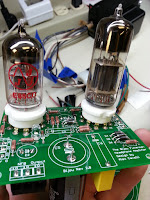
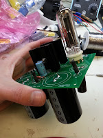
E88CC and the 6N6Pi
Debut of Tubes
Parts List was the biggest instruction
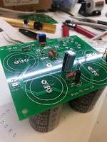
Partial Assembly
Big Caps
Assembly of the Power Supply


For some guidance, the PCBs are labeled well so the best instruction here is truly following the parts list and just doing a check list to make sure everything is where it should be. Also, as a note of caution, I have seen others mount the heatsinks and mosfets underneath the power supply board(it's the middle board in the bottom photo) and I do not believe that's wise. The heatsinks would then sit right on top of some traces and could potentially burn them to bits. I did not test this, so I could very well be worrying too much about it, but I did not want to find out after completion that my power supply traces were burning off.


They do look pretty with their tubes
Full Assembly of the Bijou

A new aspect I did not have much experience with before the Bijou was messing with transformers. I understand how they work on a circuit schematic level, but I had never used one in a project or wired one up myself. So that was interesting and a little scary because the transformer being used is the 370DAX made by Hammond Manufacturing and it pumps out two lines of 260VAC and quite frankly I did not want to find out how tingly that feels.


The board has a 250V DC output dannnnggg
Testing the Power Supply Board
 Here I was testing the power supply and to adjust a potentiometer so that it would output 250VDC.

I would consider this setup super not safe. Sure, everything is insulated, but what you don't see is that I have floated ground and have nothing running to the third prong in the event of a short.

Word to the wise( or maybe the unwise), it takes an awfully long time for the output to drop to a "safer" level of voltage even after it's been unplugged.


Enter the Toaster.

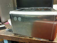
It looks nice I suppose
Bella Toaster

This may have been the poorest choice of toasters in my personal opinion, but I also did not do much research on toasters after the fact to see how much better or worse other options could have been. I think I may be mostly angry at how much of a pain it was. It is probably safe to assume any toaster would have caused me an equal amount of grief.

This particular one was chosen because I left it up to a vote for the instrument room staff at the time and this was the winner. (Maybe the lesson is don't let others vote on what you're going to be working on?)

After this project, it is my firm belief that toasters should only have bread and bread related things inside them. It is a strictly breakfast food device.


That is a hot toaster
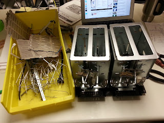
Top Cover Taken Off
Should have tagged this as NSFW
Gut Removal


This toaster had some really strange triangle shaped screws that needed to be removed to get the cover off. Maybe I should have taken that as the first sign that maybe the manufacturers don't want me taking apart their toasters to put tube amplifiers inside them.

This is where the biggest obstacles start coming into play. Where do I put the hefty transformer so it can stay hidden? How do I mount the Bijou PCBs inside the bread slot area? The goal was to make it so the tubes stuck out of the bread slots. And I know what you're thinking, will the toaster handles raise and lower the tubes? No, maybe in a future project with more toaster planning. Will it still make toast? Maybe, it does it get warm. Then what good is having your amp in the toaster if it doesn't make toast? Yes, you're now starting to see where my pain begins. In all honesty though, I have never seen an amplifier enclosed inside of a toaster and thought that novelty outweighed something more.. "practical" (boring).

Won't make anymore toast that's for sure
Cut Up Bread Slots

I decided to "hide" the transformer in the direct center of the toaster which required me to remove some of the inside material to make room for it. Another toaster fact, because the base was made entirely out of plastic and the transformer needed to sit on something didn't bend under it's weight, a 1/16 inch aluminum plate was mounted to the base for support which also served as a grounding plate later on.


Knockout punches are the greatest thing ever
Knockout holes for Left and Right Channels

Knockout punches were used to put holes in the toaster chassis for the Right and Left channel audio inputs and quarter inch headphone jack.

I also wanted to include a power entry module that used a fuse in the event that something shorted, but my grounds weren't properly tied to each other, and would pull enough amperage to blow the fuse before it blew me away.


Quarter Inch Headphone Jack
Smart looking
Mounted L/R Channels and Power

This is where I stopped because I knew the next step would be making a mounting solution and then wiring the mess together.


This is where Kyle inspired me to spend all of Saturday and Sunday of spring break getting this project restarted with the goal of finishing. Thank you Kyle. Some people just need a little push to get things started, others need help finishing things, and there is myself. Honestly though, I'm truly thankful that this is finished and I have some interesting content to provide to others.

I started by making custom bent brackets from 1/16 inch aluminum for the Left and Right channel PCBs. These were the easier of the two mounting solutions because the amplifier PCB did not have large objects underneath that I needed to avoid so I could run parallel bars and mount each board in their respective spot. Unfortunately, not everything was smooth, the boards were a very tight fit and were in contact on the edges with each other. These boards do not have a ground plane implemented and I was concerned that because I have AC running to each board for heating the vacuum tubes I should have them at least separated. So what is someone to do when PCBs mounted next to each other are touching and they shouldn't be? Why, you shave the PCBs of course. Not having a ground plane made this a lot easier and worked like a charm.
Custom is a fancy word for I didn't measure that well
Custom Bent Brackets
It eventually went in
My Woes
I have never shaved a PCB before this
L/R Channels Mounted

For both mounting solutions,  I needed to bend aluminum, but the power supply board had huge capacitors mounted underneath and it had heatsinks mounted on top so the whole board had to sit lower closer to the transformer so I could not run parallel bars without cutting some fancy shapes out which would have been much more complicated than I wanted to deal with. So I just made four custom angle brackets.

Remember how I said custom is fancy for no measuring?
Custom Angle Brackets
I know it looks pretty but that was a lengthy process
All Boards Mounted
The hacksaw fixes everything
More Woes

Naturally, all but one of the brackets needed to be "modified"(with a hacksaw) because of various things that I did not take into consideration when planning out how to mount the power supply board. The biggest complication was that I could not physically see anything underneath the board with it all in place, but everything went according to plan if we assume my plan was to get it mounted and not to get it mounted easily.


The next step now is to obviously wire everything. However, that means unmounting everything and connection wires to the boards first and then string the wires around the chassis because wires don't pass through physical objects to make your life easier(feel free to quote me on that). I know I'm going to show you five photos of various points in the wiring procedure, but this honestly took several hours to do and I was just trying to finish. I didn't take any more time to make it look absolutely spectacular, just enough to get it to work and be presentable.


I will forever refer to this as humpty dumpty
Put Back Together


Putting Humpty Dumpty back together again took a special finesse that can only be summed up as pushing wires out of the way of holes where screws would go and being gentle to not tug wires out of their screw down terminals.


It does look fantastic though
Humpty Dumpty Equipped with Tubes


Now with everything assembled this does look pretty good. Turning it on almost seems to be a shame if it doesn't work. Don't worry, it works and it looks fantastic.


Front View of the Bijou-Toast Amp


It's almost breathtaking
Bijou-Toast Amplifier On and Operational


I recorded a small video where I wasn't paying attention to what I was saying at the time while I was recording so you hear me talking a little. Also, it's another vertical video, I'm really sorry, I will try to remember to do better.

On a final note, it does work. In fact, I would say that it works really well in one channel(Left). The other channel(Right) has intermittent volume. It comes through and it can be heard, but it is much softer than the Left channel. I speculate that it could be a loose connection at either the Right channel PCB or at the headphone jack not making proper connection with the headphones. Taking it apart again to fix the issue will have to wait until I have more spare time now that school is going to resume in... six hours as I'm typing this.

This was a very interesting project; I'm much happier now that it successfully turned on, didn't short out, didn't shock me, made sounds, and is completed(ish). My recommendation is put it in a box instead of a toaster.


*EDIT (July 10, 2016): Turns out the amp works really well. It happens that I should not plug the 1/4" jack all the way in. I had to leave maybe an 1/8" sticking out at the base and both channels kicked in and sound pretty good. I don't know why it took me so long to check it. I guess I was a little discouraged at first. Long story short, everything works and it's wonderful.


Tuesday, February 23, 2016

MadCatz Alpha FightStick Modification Process

For the most part, getting the MadCatz Alpha FightStick modified was pretty straight forward with a few exceptions. I was able to successfully switch out all stock components with Sanwa parts like I had originally planned, but I'd like to go through how I did it and point out some of the issues I ran into.

In the previous blog post, I covered taking the Alpha apart and planning a little so I'm going to overlap just a bit for continuity.

gross

The guts. I needed to get all the buttons and the joystick out because they were all mashed potato feeling. Beware, the molex connectors are not easy to unclip and I broke a corner of the plastic housing on one connector trying to remove the cable. All I'm saying is just be gentle and take it slow when prying each connector out. Unclipping all the ribbon cables and removing the PCB makes it much easier to access all of them.
 

Components and everything everywhere. Super grease.
Stock Joystick

Too strong to separate.Removing the joystick should be the first step after you removed the PCB and ribbon cables. It helps keep all of that wire mess out of your working space. The stock joystick, whatever it is, was kind of interesting to remove. My initial approach would normally be to unscrew the balltop from the shaft and then remove the joystick from the chassis, but no matter how hard I tried I could not remove the ball top from the shaft. I mean the balltop is screwed on with Loctite or some other method of fusing the plastic ball to the shaft was used because I could not separate them. So I needed to remove the e-clip which can slide out from on top of the black plastic actuator. Once the e-clip is removed, the shaft with the balltop falls out and the rest of the joystick can be removed.
Here's a quick comparison of the stock joystick compared to a Sanwa JLF. There doesn't appear to be much difference and for the most part the feeling wasn't terribly different, but I did get an air of satisfaction knowing I was using the Sanwa JLF joystick(confirmation bias?). The Sanwa JLF is on the left and the stock joystick is on the right.
Look very similar.
Sanwa JLF and Alpha Stock Joystick


Buttons so short you'll flip.

After that is settled, moving to the buttons was pretty straight forward. Desolder, take out the button, put in new button, solder, and check continuity. Because, I didn't want to memorize which color went to which input on the PCB, I just swapped out a single button at a time. Since buttons, or equivalently switches, have no polarity preference you can solder the ground wire and signal wire on either side as long as you don't short the two together. It helps to stay consistent for troubleshooting later though, thankfully I didn't have to.

The buttons have a single signal wire running from one side and then the ground signal is daisy chained to the rest of the buttons. It was kind of troublesome soldering two and three wires to a single post, lots of hot finger soldering owies.


Here's a photo comparing the Sanwa buttons with the Alpha stock buttons. There is a height disparity that later on marginally effects how the PCB mounts to the chassis. The Sanwa button is on the right and the stock button is beneath the wires, but on the left.
short tall
Sanwa and Alpha Stock Button Comparison


Look at that not so great USB solder job. It passes, but I should have gone in and cleaned it up.
Once all of the new buttons were soldered in I just needed to remount the PCB, close it up, and call it done-zo. However, as I mentioned earlier, because the Sanwa buttons are taller than the stock buttons that come in the Alpha this causes mounting issues with the PCB. The PCB is supposed to sit above the buttons, and there wasn't a whole lot of clearance beneath it so when mounting it back up it is not wise to screw down those tiny bolts as tight as possible. I'm sure the PCB can handle it, but when I see fiber glass beginning to bend it always makes me nervous.
These photos are the best I could do with my camera phone to get a profile shot of how the PCB sits on top of the new Sanwa buttons. It's passable. The PCB clears the buttons in terms of critical fitting and the only consideration that needs to be made is just lightly tightening the PCB until it stops wiggling, but before the PCB starts to bend from pressure.


Put it all back together like a sandwich that you can't eat that's made of plastic, bolts, fiberglass, and lead and you get the Alpha fightstick with brand new shiny parts.  Overall, I'm pretty happy with how it turned out and also how it has improved how it feels now. Second player better be thankful that I cared enough to do this instead of giving them the pleb controller.
Nice new pink things.
Finished

4/15/2018 Update:
A user in the comments (Manu Der Fuchs) asked if it was possible to take some more photos of the internals of the Alpha fightstick. The main interest was to see what kinds of buttons were used for the L1/L2 buttons. I suspected that they were push buttons and that you could wire/solder the more conventional arcade style buttons in place. So here are the photos of the internals:


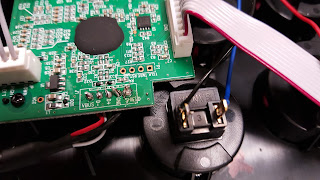
The upper PCB is where all the button circuitry for the top of the fightstick is placed. Just a few phillips screws are in the way of getting access. Pretty simple.


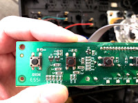
These two photos show the main board after it's been unscrewed down. The photo on the right shows the two left most push buttons are the L2 and L1 buttons with the far left being L2 and the second from the far left being L1. It should be simple enough to solder wires to the sides of push buttons without having to remove anything, but if you wanted to be really thorough you would use a multimeter in continuity checker mode and figure out which ways the buttons are oriented. I don't have any of my tools with me to give you the answer, but I can probably do that later if there's interest.  I hope this helps.